FtBP: Switching
Part 3/8
In our last discussion we covered the formation of a network packet in preparation to send that packet on the wire. Today we will cover the packet’s travel through its local VLAN from Client to Server. Let’s start by reviewing what we had in our network packet from last time. Here is where we left off:
L2-[Source MAC: 01-01-01-01-01-01 | Destination MAC: 02-02-02-02-02-02]
L3-[Source IP: 10.1.1.100 | Destination IP: 10.1.1.101]
L4-[Source Port: UDP 1025 | Destination Port: UDP 53]
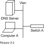
One key to remember as we go about this series is the role that each network device holds and where it sits in the OSI model. This will help us to know what we can use to route the traffic. In this article we are going to stick with switching, which is a Layer 2 function. Because of this we will only be able to look at the data contained in layer 2 of the network packet (or the Source and Destination MAC addresses). Here is our picture for this scenario:
MAC Address Basics
Lets quickly go over some attributes of a MAC address that we will need to know. MAC addresses, are intended to be globally unique identifiers. This means that no two MAC addresses in the world should be the same (This is no longer 100% true, but true enough). MAC address, for the most part, are hard coded onto the NIC card. This means that the MAC addresses have no address hierarchy (meaning that the addresses cannot be summarized by saying something like “those ten servers have MACs xx-xx-xx-xx-xx-01 through xx-xx-xx-xx-xx-10”). Because there is no hierarchy and theses addresses are hardcoded into our NICs, we have no way to predetermine where these hosts will sit on our network, and so MAC addresses are pseudo-random numbers in the perspective of your network.
The Switches Role
To clarify what we see in the picture (picture 3-1), both the DNS server and Computer A are on the same VLAN, but plugged into different ports on Switch A (VLANs being a virtual connection). For our purposes let’s say that Computer A is plugged into Int-1 and the DNS Server is plugged into Int-2. We all probably remember the days of network hubs, where every device connected to a hub, got every packet sent on that hub. Thankfully this is no longer the case with Network Switches, which instead build their own local table to help them direct packets to the correct location.
The genius of network switches is in the fact that when they receive a packet from one of their directly attached devices (i.e. – a computer plugged into one of the switchports), the Switch captures the information about the sending devices MAC address and the port it is attached to. It then stores this information in a table called a “MAC Address” or a “CAM” table. This table then acts as a “MAC to Port” mapping mechanism (much like DNS resolves a name to an IP) which the Switch needs to direct packets. Here is a sample of this for our scenario (example only):
MAC Address Interface
01-01-01-01-01-01 Int-1
02-02-02-02-02-02 Int-2
When a switch then receives a network packet it checks this table for a match to the value of the DestMAC in the network packet. If a match is found, it sends the packet directly out the corresponding port (if no match is found, it sends the packet out every port except the one it received the packet on). In this way we are able to limit the traffic that will be sent to any host on the VLAN. This means in our case after Computer A forms the packet and sends it on the wire, that the switch (assuming it already learned the DNS server’s MAC) sends the packet out Int-2 towards the DNS server.
Receiving a Network Packet
What we do with a network packet after receiving it, really shows some of the genius behind modern networks. The DNS server gets the packet from Computer A, and the first thing it does is to make sure this device (the DNS server) is the intended recipient. It does this by comparing the MAC address of the interface that it received the packet to that in the DestMAC of the packet. In this case it matches, and so it sends the packet up the network stack for further processing (Which we will get into a little later).
Lets take an aside for a moment and talk about what would have happened if the Switch did not have the DestMAC address in its MAC Address Table. It would have sent the packet out every interface it had (except the one that it received the packet on). This means that every device on the local network, including the router, would get this packet. Those who the packet was not intended for would perform the check described in the paragraph above, and because the DestMAC did not match any of their MACs, the computer would discard the packet.
So there are the basic concepts of switching logic. Switching is very simple in its operation, but beautifully designed to be repeatable, and precise.
Follow the Bouncing Packet – Series Navigation
Part1: Prerequisites
Part2: Packet Formation
Part3: Switching
Part4: Routing
Part5: Firewalls
Part6: VPN Tunnel
Part7: NAT and PAT
Part8: End-to-End, B-to-A

